But first, let’s talk about vocal effects processors and loopers!
What is a Vocal Effects Processor?
As stated in this article written by Andy Jones, the earliest notable vocal effects processor can be attributed to Alvino Rey’s Talk Box, which was created in the 1930s. Thereafter, came the vocoder, then auto-tune, then harmony effects, and so on. Over the years, a lot of vocal effects processors have been created. These electronic devices, which often have multiple built-in effects, enhance vocals by adding color and depth as one sings in real-time. Thus, such devices are used by singers especially for live musical performances. Some of the most common effects that can be seen in processors nowadays are echo, harmony, reverb, and many more. A lot of well-known vocal effects processors also come with loopers.
What is a Looper?
A looper, also referred to as a looper pedal or loop pedal, is a device for real-time recording, layering of sounds, and playback of the recorded sounds. In this article by Emma Madden, the looper is said to have originated from Terry Riley. In the ’60s, Riley incorporated tape loops to the live performance of his third album ‘A Rainbow in Curved Air’. The result of the creative layered repetition in his performance sparked what is now known as the art of looping. But, what exactly are loopers like nowadays? Based on my experience, the looper I’ve used is able to record 4 bars and have more than one loop channel. Having more than one loop channel, lets a singer or musician store different loop phrases, and then play them back at different parts of a song. Recordings can also be overdubbed multiple times with just a push of a button, creating textured backing tracks for a more engaging and full-sounding live performance. It is very clear that looper devices have definitely come a long way since the 60s.
What are some of the most popular vocal effects processors and loopers?
What’s common with all the vocal effects processors and loopers available in the market?
Yes, you’ve guessed it! They are either a pedal or a tabletop vocal effects processor and looper.
Now, imagine a wearable vocal effects processor and looper that allows you to control a vocal effect, just by changing the position of your hand…
Introducing, MINI VOX!
With vocalists in mind, MINI VOX will be the perfect device for enhancing and manipulating one’s vocals during any part of their performance– whether it be adding more delay effects to just the last word of a musical phrase or cutting out the reverb abruptly for artistic effect. Whatever the intention is, this device will allow vocalists to have total control plus real-time enhancement and manipulation of vocals using gestural movement, at any point of a song.
Why aren’t their photos or videos of MINI VOX, you ask? Well, it’s because it is just in the prototype stage. It should also be noted that due to lack of time and resources, this will not be available in the near future. Nonetheless, this is the big idea:
A pair of electronic devices that communicate with one another. The board on the left side is the main controller, which will have inputs for microphones, and outputs for connections to a computer and speaker systems. The image on the right side is a seamless wearable device that has four modifiable buttons. In its initial state, there will be 2 buttons for toggling between vocal effects and other settings, 1 button for starting and stopping a loop phrase recording, and 1 button for clearing the recorded loop phrase. Ideally, these buttons will be modifiable to suit the needs of the user. In any case, further research is needed in order to fully realize this idea.
So, what’s the purpose of MINI VOX and why was it created then?
MINI VOX was created for my Interfacing for Audio and Music module coursework assessment at the University of York. The task for the assignment is to research the history and current state of my chosen area, and decide what challenge I want to address. Then, to demonstrate the challenge being addressed, a system which interfaces electronic sensors to a microcontroller using common electronic components must be designed and built. This system should also be capable of producing sounds and/or visuals in PD, Max/MSP, or other external synthesis system.
As you may have noticed, the challenge I have chosen is the absence of wearable gestural controlled vocal effects processors and loopers in the market. I have done a bit of searching and have not seen a device like this yet. So, it makes me wonder why this hasn’t been done yet. Is there no need for this? Is it too difficult to mass produce? Or are there companies developing such a device already and we just don’t know about it yet? But, instead of dwelling on these questions, I’ve decided to put matters into my own hands by trying to design and build my own wearable vocal effects processor and looper for the coursework assessment. As someone who is new to electronics and programming, my goal for this is to see what the possibilities are for designing and building such a device. The result of this attempt is the creation of the MINI VOX patch and circuit.
So, what is the prototype like, you ask? See for yourself…
This video gives an overview of the patch and circuit.
This is the demonstration video of the prototype.
As you can see from the video, the prototype is definitely working. The buttons are able to trigger functions in the patch, and some effects can be controlled by gestural movements. Obviously, there’s still a lot of room for improvement. However, the prototype surely proves that the big idea is not impossible.
If YOU also want to take matters into your own hands by creating your own prototype, follow my how-to guide here.
This guide walks you through how to create the MINI VOX patch and circuit. There are five steps in total. All of the patches and codes used are provided in this guide. To download these, simply click on the links. By the way, if you haven’t read what this is all about and you haven’t seen the MINI VOX videos yet, then please check out the main page here.
All set? Let’s get started!
STEP 1: Create the vocal effects processor patch
MINI VOX Max 7 Patch
The first step is to create the MINI VOX patch. This was created in Max 7, but this can be created in PD too. The patch is designed in a simple yet detailed manner for ease of use and navigation. It has a color scheme that is cool and easy on the eyes for aesthetic purposes. Everything is labeled and useful notes were placed where appropriate. The patch is divided into 2 main sections– Audio Settings and Vocal Effects. The Audio Settings section is divided into two parts– Microphone and Main Out. The Microphone part contains a mic on/off button, a meter, and a dry gain slider. The mic on/off button is an ezadc~ interface object that converts the analog signal to a digital signal. Essentially, this is for both audio input and turning the audio on/off. Below this button is a meter~ interface object which shows the peak amplitude of the microphone’s audio signal. Then, on the right, there is a dry gain slider object for listening only to the dry signal or raw sound coming from the mic. Below the microphone settings is the Main Out settings. As seen in the image above, there is a main out on/off button on the left side and a live gain slider on the right side. The main out on/off button is an ezdac~ interface object that converts the digital signal to an analog signal. This is for both the audio output and turning the audio on/off. The live gain slider, on the other hand, is for controlling the overall gain.
The vocal effects section contains 3 vocal effects and a looper. The vocal effects are– Delay, Reverb, and Harmony. The Delay effect allows the user to play around with the delay time and the delay amount. The reverb effect allows the user to input the liveness amount and output level, as well as to adjust the overall reverb volume. For the harmony effect, the voices are fixed, but users can increase or decrease the volume of the voices by adjusting the volume slider. Below are screenshots of the subpatches containing the effects:
Delay:
Reverb:
Harmony:
The looper has an on/off toggle at the top. To start recording a loop, users hold down the space bar while recording a musical phrase. To stop recording the loop, users need to release the space bar. A CLEAR LOOP button is included for deleting the recorded loop. Below these are a pair of sliders. The first slider is for increasing the volume of the recorded loop. The second slider is for hearing the click track, if the user would like to use one. At the moment, there is only one bpm. Future versions of this patch would most likely see a modifiable click track. Below is a screenshot of the looper subpatch:
Please note that the patches or codes used for the delay, reverb, harmony, and looper are only slightly modified by me. The original creators of the codes used are as follows:
Delay: Multi-tapout~ delay code by Jacob Sachs-Mishalanie as seen here
Reverb: Audio Processing Reverb code by David Tinapple and Sharon McCaman as seen here
Harmony: Pitch Shifting code by Sam Tarakajian (aka dude837) as seen here
Looper: Boomerang! code by Sam Tarakajian (aka dude837) as seen here
In its simplest form, the diagram below shows how the main patch works:
MINI VOX Patch Connection Diagram
Looking at the diagram above, it shows that the microphone signal goes into the delay, reverb, harmony, looper, meter, and dry gain. The dry gain goes into the live gain, then into the main out. For the effects, all three are linked to one another to cover all possible effects combinations that users would like to use. Before going into the live gain and then to the main out, all three effects are passed through the looper.
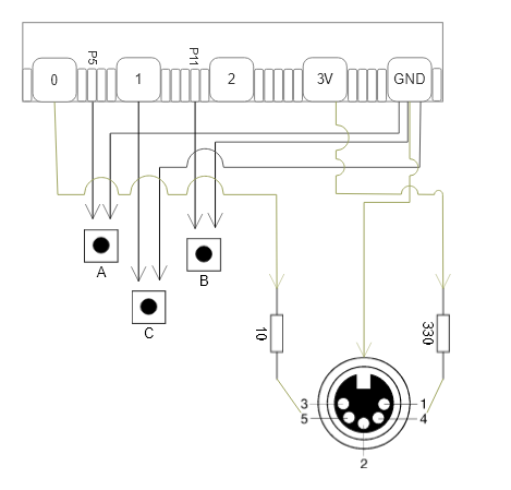
The built-in A and B buttons on the micro:bit are connected to pins 5 and 11, respectively. The additional button C, is connected to pin 1. All three buttons are also connected to GND for grounding them. For the MIDI, pin 0 is connected to the MIDI connector pin 5 with a 10 ohm resistor in between. Additionally, pin 3V is connected to the MIDI connector pin 4 with with a 330 ohm resistor in between. Lastly, GND is connected to MIDI connector pin 2 for grounding it.
Now that you have an idea, we’re now ready to assemble the components!
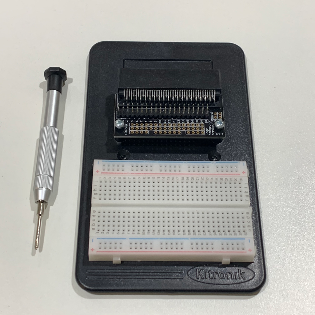
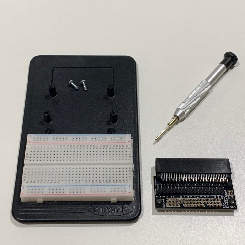
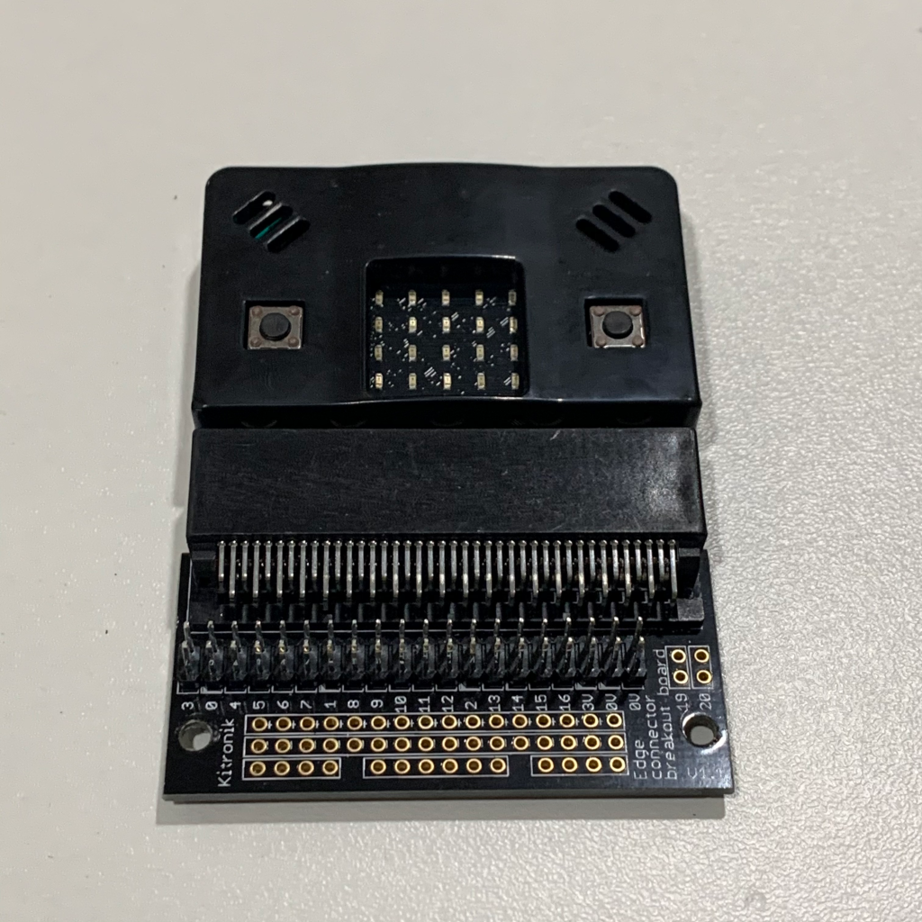
Step 3.1: Detach the edge connector breakout board from the prototyping kit by using the screwdriver to unscrew the screws. This is necessary so that later on, only the edge connector breakout board and the micro:bit are attached to the hand.
3.1 (a)
3.1 (b)
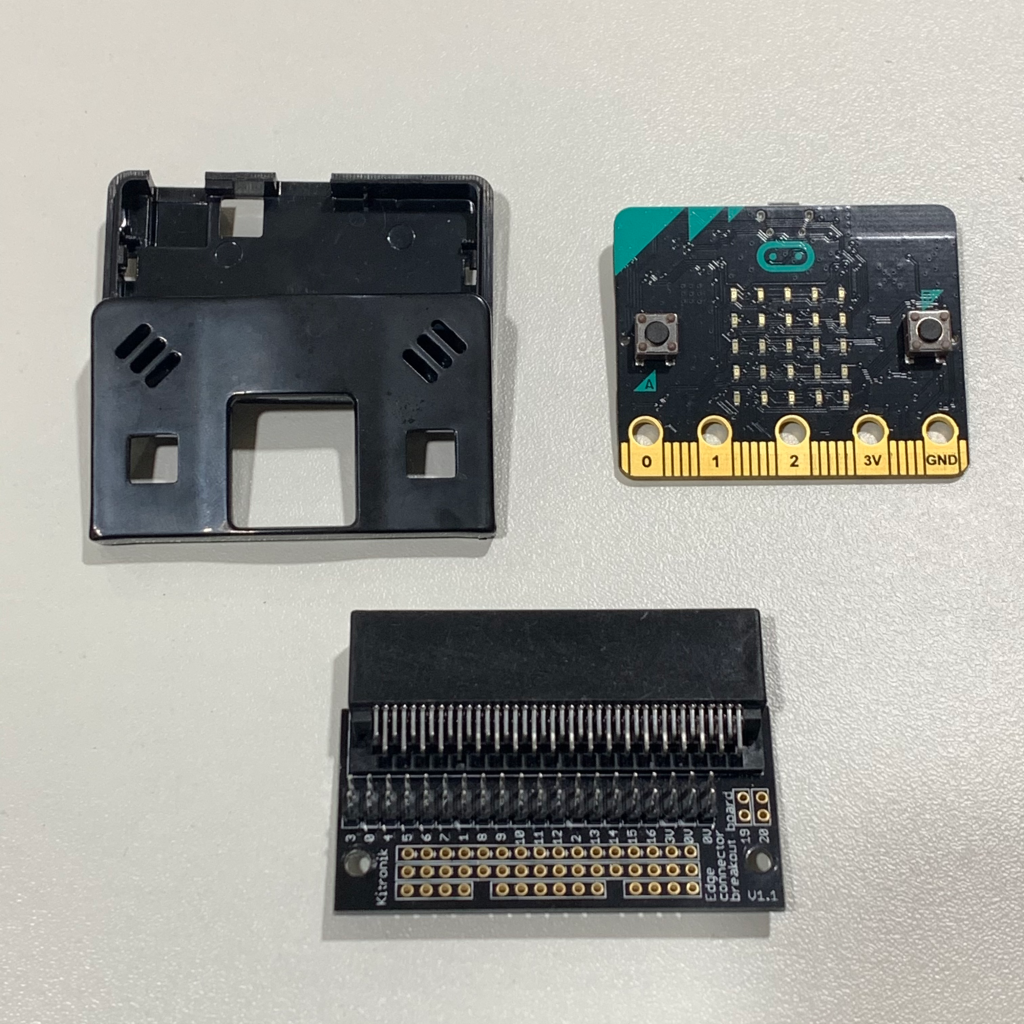
Step 3.2: Place the protective case on the micro:bit, then attach the micro:bit to the edge connector breakout board.
3.2 (a)
3.2 (b)
3.2 (c)
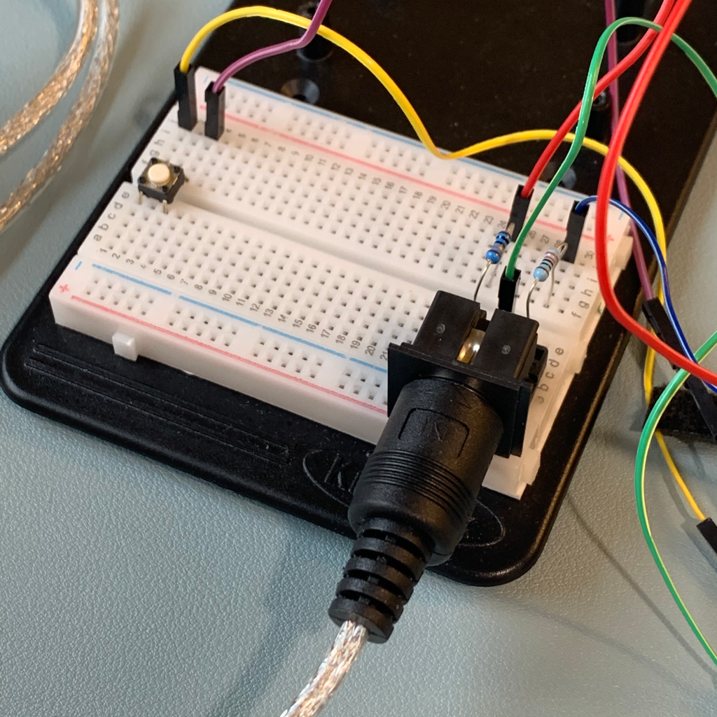
Step 3.3: Mount the MIDI PCB mount DIN on the breadboard. Keep in mind that pins should be on separate rows.
3.3 (a)
3.3 (b)
Step 3.4: Take 2 female-to-male breadboard leads, connect them to one another. Connect the female end to pin 0 of the breakout board and connect the male end to the row aligned with MIDI connector pin 5. After, attach the 10 ohm resistor in between pin 0 and pin 5 on the same row.
3.4 (a)
3.4 (b)
3.4 (c)
3.4 (d)
Step 3.5: Take 2 female-to-male breadboard leads, connect them to one another. Connect the female end to pin 3V of the breakout board and connect the male end to the row aligned with MIDI connector pin 4. After, attach the 330 ohm resistor in between pin 3V and pin 4 on the same row.
3.5 (a)
3.5 (b)
3.5 (c)
Step 3.6: Take 2 female-to-male breadboard leads, connect them to one another. Connect the female end to pin 0V of the breakout board and connect the male end to the row aligned with MIDI connector pin 2 to ground the circuit. The MIDI OUT circuit, should be working now.
3.6 (a)
3.6 (b)
3.6 (c)
Step 3.7: Mount the PCB push button in the middle of the breadboard, on the first few rows. Take 2 female-to-male breadboard leads, connect them to one another. Connect the female end to pin 1 of the breakout board and connect the male end to the row aligned with the top terminal of the button. Take another pair of female-to-male breadboard leads, connect them to one another. Connect the female end to pin 0V of the breakout board and connect the male end to the row aligned with the bottom terminal of the button.
3.7 (a)
3.7 (b)
3.7 (c)
3.7 (d)
3.7 (e)
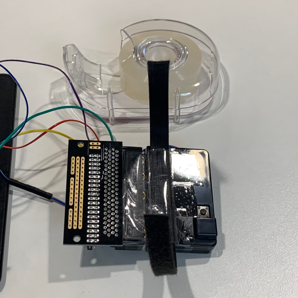
Step 3.8: Take the velcro then cut out a strip that fits around your hand. Secure the velcro strip to the back of the micro:bit and breakout board using some tape.
3.8 (a)
3.8 (b)
3.8 (e)
Step 3.9: Finally, attach one end of the USB cable to the micro:bit, and the other end to your computer. Then, attach the MIDI IN of the MIDI-to-USB cable to your circuit, and the USB to your computer.
3.9 (a)
3.9 (b)
STEP 4: Programming the prototype
After assembling the circuit, the next step is programming the micro:bit. This can be done in mu-editor or in BBC micro:bit’s online Python Editor. The code used can be seen below, but you can also download the .hex and .py files here.
from microbit import *
import math

# Codes from the I-AM Module Labs of the University of York
# Slightly modified by Francesca Lorico

# MIDI ON triggered by micro:bit buttons
def midiNoteOn(chan, n, vel):
    MIDI_NOTE_ON = 0x90
    if chan > 15:
        return
    if n > 127:
        return
    if vel > 127:
        return
    msg = bytes([MIDI_NOTE_ON | chan, n, vel])
    uart.write(msg)

# MIDI OFF triggered by micro:bit buttons
def midiNoteOff(chan, n, vel):
    MIDI_NOTE_OFF = 0x80
    if chan > 15:
        return
    if n > 127:
        return
    if vel > 127:
        return
    msg = bytes([MIDI_NOTE_OFF | chan, n, vel])
    uart.write(msg)

# MIDI CC triggered by micro:bit accelerometer
def midiControlChange(chan, n, value):
    MIDI_CC = 0xB0
    if chan > 15:
        return
    if n > 127:
        return
    if value > 127:
        return
    msg = bytes([MIDI_CC | chan, n, value])
    uart.write(msg)

# Initialization
def Start():
    uart.init(baudrate=31250, bits=8, parity=None, stop=1, tx=pin0)

# Main Program
Start()
# Most recent values of buttons and Accelerometer
lastA = False
lastB = False
lastC = False
BUTTON_A_NOTE = 36
BUTTON_B_NOTE = 37
BUTTON_C_NOTE = 38
last_tilt_x = 0
last_tilt_y = 0

# While loop of the program
while True:
    # buttons
    a = button_a.was_pressed()
    b = button_b.was_pressed()
    c = pin1.is_touched()
    if a is True and lastA is False:
        midiNoteOn(0, BUTTON_A_NOTE, 0)
    elif a is False and lastA is True:
        midiNoteOff(0, BUTTON_A_NOTE, 0)
    if b is True and lastB is False:
        midiNoteOn(1, BUTTON_B_NOTE, 0)
    elif b is False and lastB is True:
        midiNoteOff(1, BUTTON_B_NOTE, 0)
    if c is True and lastC is False:
        midiNoteOn(2, BUTTON_C_NOTE, 0)
    elif c is False and lastC is True:
        midiNoteOff(2, BUTTON_C_NOTE, 0)

    # Current X Y of accelerometer
    current_tilt_x = accelerometer.get_x()
    current_tilt_y = accelerometer.get_y()

    # X Y of accelerometer to MIDI (0 - 127)
    if current_tilt_x != last_tilt_x:
        mod_x = math.floor(math.fabs((((current_tilt_x + 1024) / 2048) * 127)))
        midiControlChange(0, 20, mod_x)
        last_tilt_x = current_tilt_x
    sleep(10)

    if current_tilt_y != last_tilt_y:
        mod_y = math.floor(math.fabs((((current_tilt_y + 1024) / 2048) * 127)))
        midiControlChange(0, 21, mod_y)
        last_tilt_y = current_tilt_y
    sleep(10)
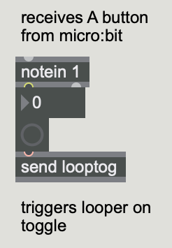
Before programming the micro:bit, it is first important to think about how you want the circuit to control the patch. For this prototype, it has been decided that the buttons on the micro:bit, as well as the additional button on the breadboard will trigger looper controls of the patch. The A button triggers the on/off button of the looper, the B button triggers the start and stop loop recording function, and the additional button triggers the clear loop function. Each button is labeled as a, b, and c respectively in the code above. On the other hand, the X and Y accelerometer coordinates of the micro:bit is dedicated to changing the values of the delay amount and reverb output level of the patch.
In order for the micro:bit to trigger controls on the patch, communication between the two must be established. This is where MIDI ON, OFF, and CC come into play. MIDI ON and OFF are needed for letting the patch know when a button is pressed or released, whereas MIDI CC is used for sending control change events. After these are defined in the program, an initialization statement needs to be added. The next step after this is to code the main program. In this part, it is necessary to define the most recent values of the variables first, then write a while loop after. The loop contains newly defined variables for the buttons that need to be set to have specific functions. For instance, button a was assigned the function was_pressed to indicate that the button was indeed pressed. More information on button functions can be found here. After the variables, an if-elif statement for the buttons follows. Below this is an if statement for the accelerometer.
After flashing or saving the code to the micro:bit, the next step is to add objects to the patch which will receive the MIDI messages sent out by the micro:bit. Below are images indicating the objects added in the patch:
A Button
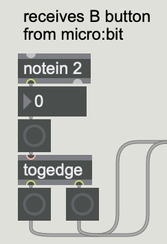
B Button
C Button
X Accelerometer
Y Accelerometer
To receive the button messages, a notein object needs to be added to the patch. The argument that follows notein is the channel where the message is being received. 1 is for the A button, 2 is for the B button, 3 is for the C button. The messages are then sent to the intended functions in the patch. For the accelerometer message, a ctlin object needs to be added to the patch. The arguments following ctlin are the controller number and channel where the data from X and Y coordinates are received. After this object, a scale object is added in order to scale the values from the accelerometer so as to fit the range of the sliders. Then, these are sent to the intended functions in the patch as well.
STEP 5: Enjoy the prototype!
The final step in this how-to guide is to run the patch, test out the prototype, and just have fun with it! Once you’re more familiar with how it works, why not try adding more effects or functions?
That’s all to it. Have fun!
Thoughts on possible future work:
Programming the same buttons to have multiple functions. For example, instead of having a separate button for clearing the recording, it would be more efficient if pressing A+B could do this. Doing so would allow other functions to be programmed to the additional push button.
Programming dedicated buttons or a potentiometer for switching between effects.
Adding potentiometers for controlling the volume sliders of effects.
Adding more effects, multiple loop channels, and a modifiable click track.